General Information
The SMRT-100 consists of a factory installed low-voltage 5” high-resolution color touchscreen display, mounted on the front panel of the walk-in beside the door, a power/device wiring base installed in a weatherproof non-metallic box on top of the walk-in, and a single combination sensor for measuring both temperature and %RH inside the walk-in.
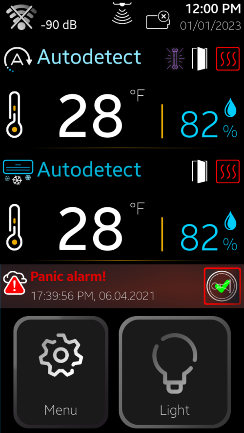
With the connection of a second sensor, the SMRT-100 can continuously monitor and display information for up to two separate rooms simultaneously.
The system may be enhanced by adding an optional SmartRite low-voltage pushbutton light switch installed on the same front panel as the SMRT-100, inside or outside of the walk-in room(s), and an optional SmartRite panic pushbutton installed inside the walk-in to activate an alarm in case of entrapment or other operator emergency.
The SMRT-100 also has the capability to use an optional interior mounted low-voltage motion sensor to control the lights, and/or an optional magnetic door switch to turn the lights on and/or automatically turn the evaporator coil blower fans off at entry.
The SMRT-100 has the capability for multi-way light switching from multiple door locations with the use of the low-voltage SmartRite switches (no 3 or 4-way required) and can modulate door jamb and view-port window heat as a percentage of time-on and time-off to save energy.
The SMRT-100 is set to “English” as the default language. If “Spanish“ is the preferred language, it may be
selected from the Main Menu->Select Language setting.
To access the settings menu:
If the password is correct, you will have access to the Main Menu Settings.
Field Connection
Initial Wiring
Locate the conduit wiring stubs that protrude from the top of the door panel with the SMRT-100 display, switch (if applicable) and panic button (if applicable) installed. These stubs contain the 2, 3 or 4-conductor low voltage cable used to connect the devices to the power base. Mark and drill the ceiling panel(s) that sit on top of the door panel for the conduit stubs to pass through for access on top of the ceiling panel.
The Temperature and RH sensor should be mounted on the wall behind and to the left of the evaporator coil. They are each provided with 30’ of lead wire for connection to the Power Base. The sensor housing may be adhered to the wall using double-sided adhesive tape or by using a plastic wire tie with a screw mounting hole, and the lead wires may be routed along the ceiling for exit through the top corner of the doorway, or lead wires may be routed through a small ¼” diameter hole drilled through the ceiling panel and sealed with RTV Silicone sealant. Sensor leads should be routed to the non-metallic Power Base enclosure just as for the device leads.
Power Base Mounting
On INDOOR walk-ins only, locate the SmartRite Power Base module with non-metallic weatherproof enclosure on the roof of the walk-in in a readily accessible location and as near as possible to the conduit wiring stubs with the low voltage cables. On OUTDOOR walk-ins with a membrane roof cap, locate the Power Base module and enclosure at the top of the exterior wall with the closest accessibility to the wiring stubs and low voltage cables Each cable should be routed across the top of the ceiling panel and to the Power Base enclosure for connection to the Power Base.
Drill three each 7/8” diameter holes through the side of the non-metallic Power Base enclosure – one for device and sensor wiring, one for power wiring and one for light wiring. Install a ½” conduit size membrane cable seal fitting where the device cables will pass through and into the enclosure. ½” conduit fittings and associated conduit are to be installed from the power supply and light wiring stub as applicable. Once the device cables are routed and secured with adequate slack to prevent damage and are inserted through the fitting and into the enclosure, components are ready to be wired to the Power Base.
Power Base Wiring
Warning
To avoid damaging the electronic boards, ALWAYS put the TFT in Sleep Mode after disconnecting the power from the cold room because the system has a back-up battery connected to the display module that provide power to the base module, panic and external switches(see Sleep Mode Section).
In Sleep mode battery is disconnected from the base module. To reconnect the back-up battery just plug the main power to the system.
Connect the 4-conductor low voltage color-coded cable (r-red, gr- green, w- white, bk-black) from the SMRT-100 TFT display to the corresponding color-coded terminals marked “DISPLAY”, terminals 60, 59, 58 and 57 (see Power Base Wiring).
Connect the 4-conductor low voltage color-coded lead (r-red, gr- green, w- white, bk-black) from the Temperature and RH Sensor to the corresponding color-coded terminals marked “SENSOR1”, terminals 56, 55, 54 and 53 (see Power Base Wiring).
Note
Up to two rooms may be monitored with the use of a second sensor mounted in the second room and connected to terminals marked “SENSOR2”, terminals 52, 51, 50 and 49 (see Power Base Wiring).
A low-voltage (DO NOT USE LINE VOLTAGE) magnetic door switch, supplied with the SmartRite Monitor/ Alarm, may also be connected where door activated lighting and evaporator fan control are desired, or where door-open monitoring/alarm is desired. The door switch is supplied with low voltage leads that must be routed through the ceiling as previously described for the temperature sensor and device wiring cables back to the Power Base on top of the ceiling. Connect the 2-conductor low voltage color-coded cable (w-white, bk-black) from the door switch to the corresponding terminals marked “DSw1”, terminals 48, and 47 (see Power Base Wiring).
Note
up to two doors may be monitored with the use of a second magnetic switch mounted on the second door and connected to terminals marked “DSw2”, terminals 46 and 45 (see Power Base Wiring).Connect the 3-conductor low voltage color-coded cable (r-red, w- white, bk-black) from the external SmartRite push button light switch to the corresponding color-coded terminals marked “ELgt”, terminals 25, 24 and 23 (see Power Base Wiring).
Note
Up to three individual SmartRite light switches may be connected to the Power Base for control of lights from any of three rooms (R1, R2 and R3 - see Power Base Wiring).
Connect the 4-conductor low voltage color-coded cable (r-red, gr- green, w- white, bk-black) from the Panic push button switch to the corresponding color-coded terminals marked “PANIC”, terminals 32, 31, 30 and 29 (see Power Base Wiring).
Note
Up to three individual SmartRite panic switches may be connected to the Power Base for panic alarm activation from any of rooms ( see Power Base Wiring).
A low-voltage (DO NOT USE LINE VOLTAGE) motion detector, available as an option with the SmartRite Monitor/ Alarm, may also be connected where motion sensing lighting control is desired. The motion detector is supplied with low voltage leads that must be routed through the ceiling as previously described for the temperature sensor and device wiring cables back to the Power Base on top of the ceiling. Connect the 3-conductor low voltage color-coded cable (r-red, gr- green, bk-black) from the motion detector to the corresponding color-coded terminals marked “MOT”, terminals 28, 27, and 26 (see Power Base Wiring).
Note
Up to three individual motion detector switches may be connected to the Power Base for motion activation of all lighting from any of three rooms (R1, R2 and R3 - see Power Base Wiring).
Light Wiring
Connect the wiring from the room lights (field-installed, wiring and conduit from lights run by field electrician) to the Power Base terminals marked “LIGHT”, terminals 6 (*BK-LGT), 7 (WH-N) and 8(GR-G) (see Power Base Wiring). *Please note that this must not be a switched leg, but must be direct from the line side of the light fixture wiring).
Power Wiring
Connect the 120VAC power wiring from a 15 Amp overcurrent protected supply circuit directly to the Power Base terminals marked “POWER”, terminals 1 (BK-L), 2 (WH-N) and 3(GR-G) (see Power Base Wiring).
Startup and Operation 2.0
Apply 120VAC, 60hz, 15amp power. After a few seconds, the Home-Screen is displayed, indicating cold-room functional parameters:
- room temperature(s) and %RH corresponding to the room(s) where the sensor(s) are mounted.
- device alarms
- device status: Wi-Fi connection status, real-time clock, and date, door heater(s) status, etc.
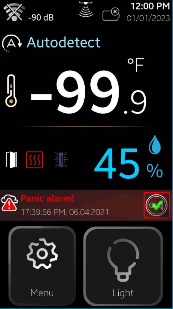
Home-Screen for the device, possible configurations:

Home Screen Structure

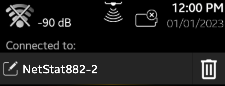
Home Screen Status Bar
Note
If Wi-Fi connection = OFF, no icon will be displayed.
Wi-FI Connection
 = No Wi-Fi network was selected = No SSID and password was saved by the system�
 = Wi-Fi No Internet
 = Wi-Fi Not Configured
 = Wi-Fi Connected to the internet
 = Connected to Server
Rechargeable Battery Status
 = 0 %
= 0 % = 25 %
 = 50 %
 = 75 %
 = 100 %
 = Charging
 = No Battery
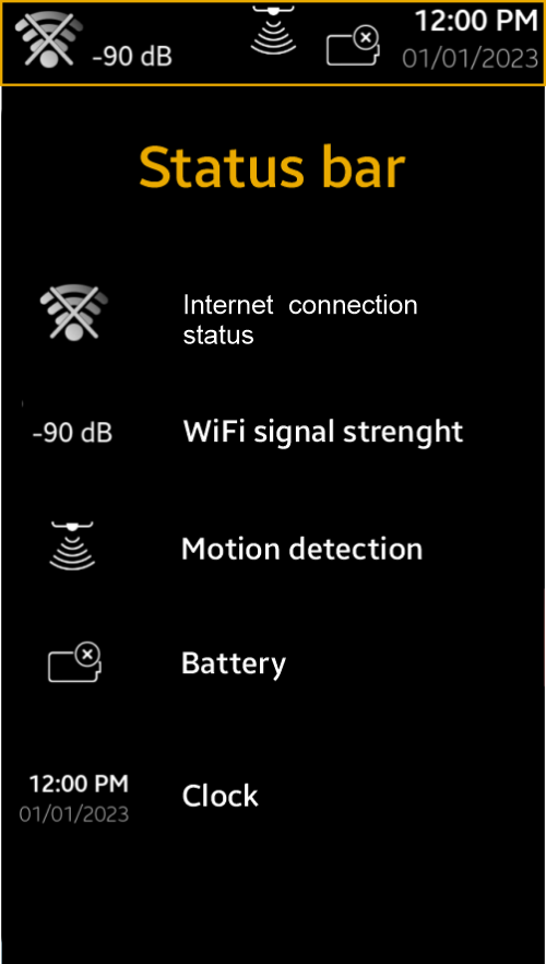
Real Time Clock
08:25:01 AM = hh : mm : ss and AM/PM
07/18/2022 = month / day / year
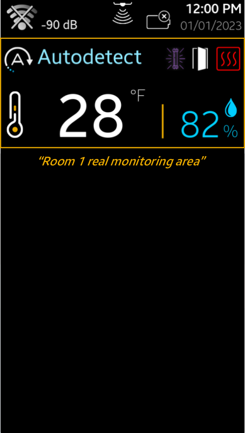
Room 1 Real-time Monitoring Area
In this area the functional parameters for room 1 are indicated:
Room 1 type:
Cooler, Freezer, or Auto*
*indicated until the system automatically detects the type, if the system is set to autodetect the room type.
Temperature
Measured in Room 1 in°F or °C according to system settings
Humidity
[ % ] measured in Room 1Door Open Indicator 
Indicates if the room door is opened, ; if closed – the icon is hidden
Door heater for room 1 
indicated only when the heater is on. The heater is on only when the room temperature goes under a settable value (ex. Docs 35°F), set by the Start Air Temperature
Note
The door heaters are on/off according to a PDM (Pulse Duration Modulation) cycle
with an 8-minutes period; the on-time is set by the Percentage parameter in Menu ->
Settings (see 3.1.4 for details).
Example
If the Start Air temperature is set to 35°F and the Percentage is set to 60%, it means that as long as the air temperature inside room 1 goes under 35°F, the door heater will be on for 4.8 min. (60/100 x 8min and off for 3.2min.).
Motion Detector Indicator
if the motion detector switch is active, the icon is visible only when motion is detected in room 1; in this case, the light is set on.
Note
The motion is active only if the Motion Detector Switch parameter is set to YES in Technician Menu (see 3.2.4 for details).
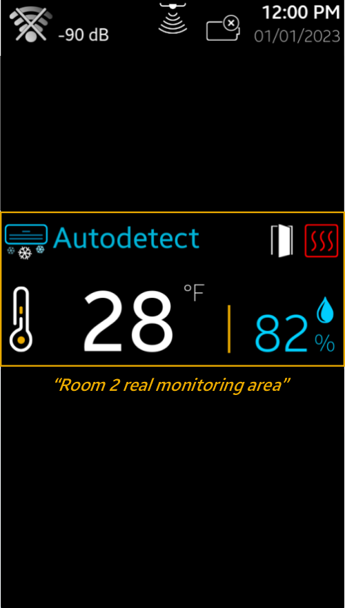
Room 2 Real-time Monitoring Area
Similar to Room 1 real-time monitoring area.
Note
If only one room is installed, Room 2 Real-time Monitoring Area is hidden and Room 1 Real-time Monitoring Area will extend over it.
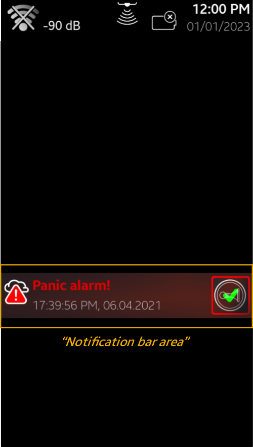
Notification Bar
If there are any active device alarms, the Home Screen will display a red Notification Bar, indicating the corresponding alarm description and time and the alarm will sound.
- “High Temp. Alarm”
- “High Temp. Alarm”
- “Low Humidity Alarm”
- “Panic Alarm”
Examples
Note
Press  to stop the buzzer beeping. The buzzer symbol will turn grey. This
silences and resets the alarm beeper, however, the visual alarm(s) will still be displayed
as long as the alarms remain active.
to stop the buzzer beeping. The buzzer symbol will turn grey. This
silences and resets the alarm beeper, however, the visual alarm(s) will still be displayed
as long as the alarms remain active.
If multiple alarms are active simultaneously, press the Notification Bar to access the Alarm Menu Screen.
Press for every active alarm to stop the buzzer beeping. The buzzer symbol will
mark it. This silences and resets the alarm beeper, however, the visual alarm(s)
will still be displayed as long as the alarms remain active
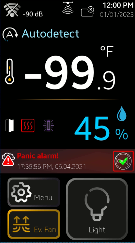
Navigation Bar
Contains the buttons to navigate to Menu and the rooms Light Switch.
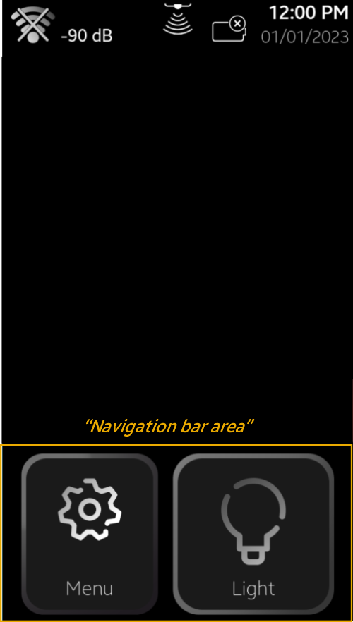
 Menu
Menu Light Switch
 Evaporator Fan Switch
Press Menu to access the programming menu.
Light switch turns on and off the light in the rooms.
If evaporator fan switch is installed and enabled in Technician Settings the a Evaporator Fan button will appear at the bottom of the menu button.
To avoid displacing cold air with warm air when users are opening the door, press Evap. Fan Switch and the evaporator fan will stop blowing when the door is opened; the fan will restart according to user-selectable time and temperature conditions (see 3.1.5 for details on how to set up this function).
Setup 3.0
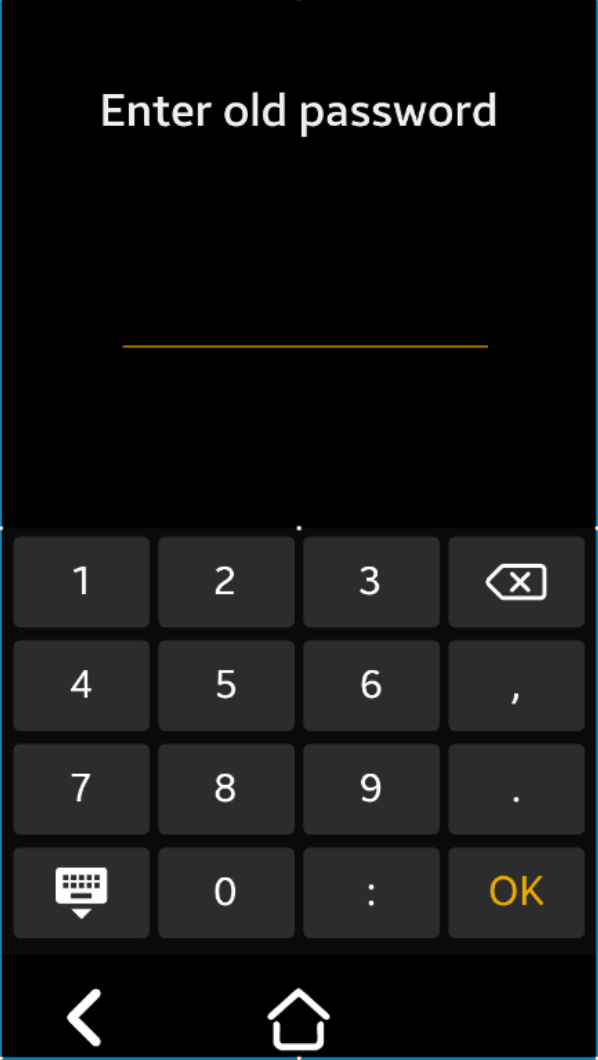
To access the settings menu:
The default password is: 1 2 3 4
If the password is correct, you will have access to the Main Menu Settings.
Note
The Menu Password can be modified by the user; access Menu->Change Password
The menu password is a 4-number format pin code.
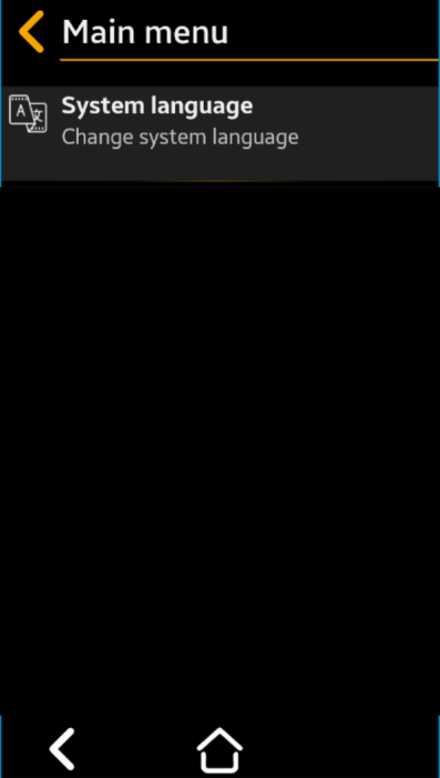
Main Menu
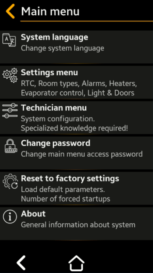
Main menu screen
Categories
- System language - To change system language (Default: English; Available option: Spanish)
- Settings menu - Containing setup of: Real Time Clock , Room Types , Alarms, Heaters, Evaporator, Light and Doors
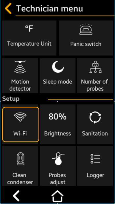
- Technician menu - Containing setup of: Device measurement unit, Panic switch, Motion detector, Sleep mode, Number of probes, Wi-Fi, Display Brightness, Sanitation, Condenser, Probes Adjust and Logger
- Change password - To change main menu access password
- Reset to factory settings - To load default parameters and counter of number os forced startups
- About - Here you see and edit general information about device like: Device name, Hardware version, Software version, Manufacturing date , Installed room name (x2)
Date and time
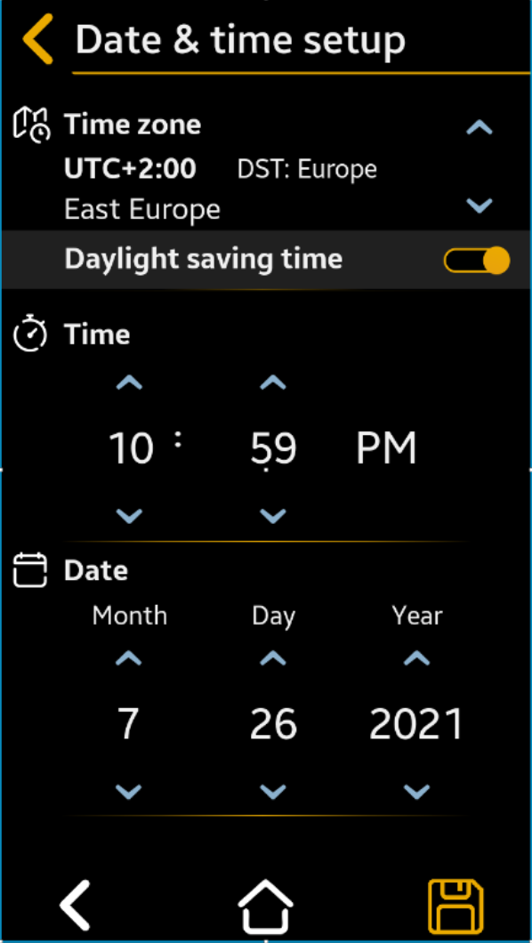
Date and Time Setup
- Hour – advance < > to current, AM or PM
- Minute – advance < > to current
- Month, Day, Year – advance < > to current
- Time Zone – advance < > to current (Default = UTC – 4:00 Atlantic Time)
- Daylight Savings Time – < > to “Yes” or “No” (Default = Yes)
Press " Save” to save, then “
 Back” or “Back” to cancel the selection
Note
If the system is connected to the Internet, the RTC will be synchronized automatically.
Important
Manually set up the Time Zone and Daylight Saving Time according to your local requirements.
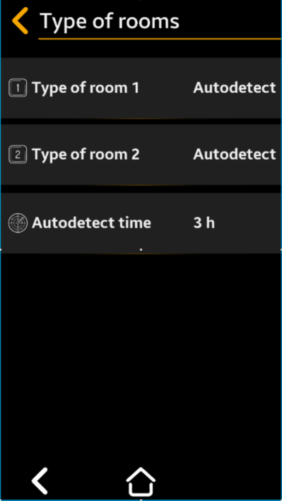
Rooms Types Setup Menu
Used to set the room type (cooler or freezer). The functional parameters, alarms and warnings will be set automatically according to the selected type. During installation, you can choose the autodetect function. In the user selectable autodetect time, the system will automatically detect the installed room type and set parameters accordingly.
Select to “Cooler”, “Freezer”, or “Auto”*
(Default = Cooler)
Note
*Auto setting will automatically detect room type after “Autodetect time”
Press " Save” to save, then “Back” “Back” to cancel the selection
Repeat the procedure as for Room #1 Type
Autodetect Time Setup
Select to set 1 to 12 hours for SMRT-100 to automatically detect room type accordingly (Default = 1 hour)
Press " Save” to save, then “Back” “Back” to cancel the selection
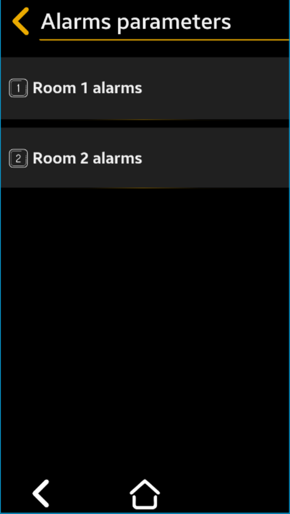
Room #1/Room #2 Alarms parameters
First select the room to set the functional parameters for.
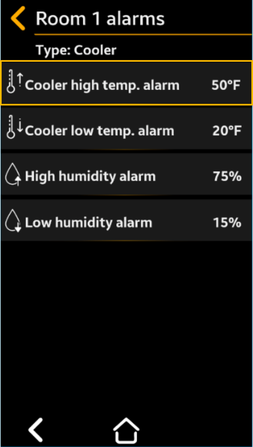
Temp. High Alarm
advance Select to desired alarm
temperature
Cooler default = 45°F
Freezer default = 20°F
Room type is indicated at the top of the menu
This is an example of how values are being modified inside menu sections
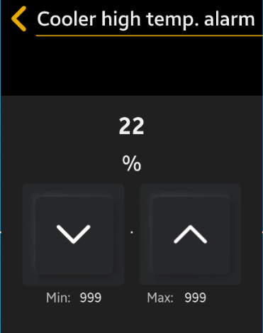
Value: 45°C - is the value you want to set your parameter
Value: 50 (upper) & -20 (lower) - represents the interval of the minimum and maximum values.
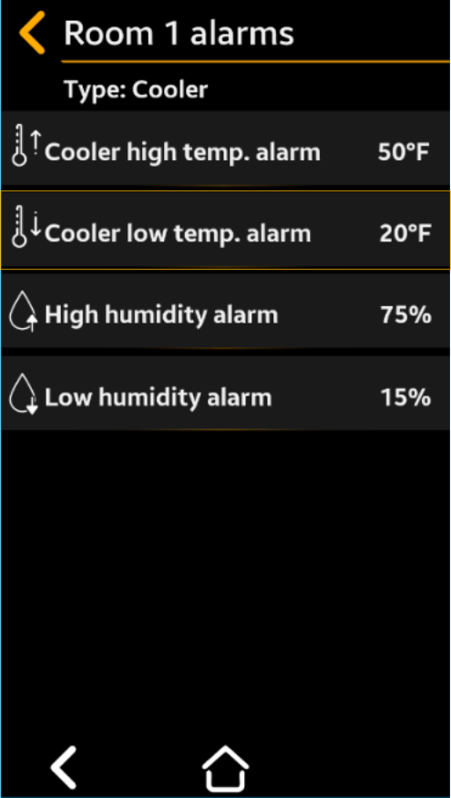
Temp. Low Alarm
Select to desired temperature
Cooler default = 33°F
Freezer default = -25°F
Room type is indicated at the top of the menu
Press " Save” to save, then “Back” “Back” to cancel the selection
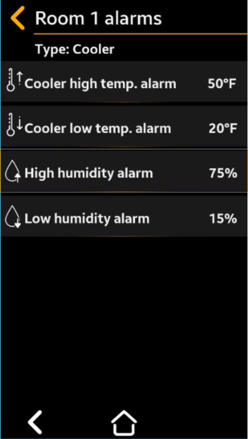
Humidity High Alarm
Select to desired humidity
Cooler default = 80°F
Freezer default = 75°F
Room type is indicated at the top of the menu
Press " Save” to save, then “Back” “Back” to cancel the selection
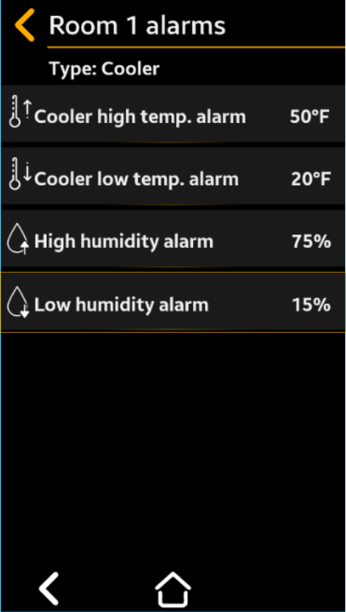
Humidity Low Alarm
Select to desired humidity
Cooler default = 30°F
Freezer default = 35°F
Room type is indicated at the top of the menu
Press " Save” to save, then “Back” “Back” to cancel the selection
Room #2 Alarms only available if 2 sensors are set
in the Technician Menu- Repeat the procedure as for Room
#1 Type
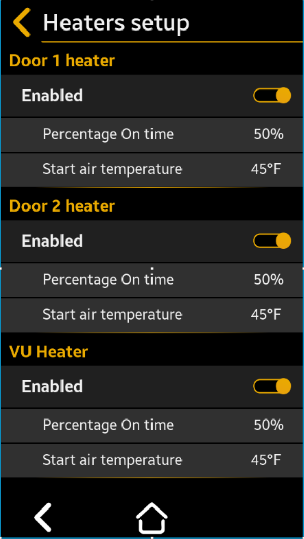
Heaters Setup
Used to set the door heaters and window heater control parameters according to the programmed room type (cooler or freezer). The door heaters are on/off according to a PDM cycle with an 8-minute period; the on-time is set by the Percentage parameter in Menu Settings (see 3.1.4 for details). For example, if the Start Air temperature is set to 35°F and the Percentage is set to 60%, it means that as long as the air temperature inside room 1 goes under 35°F, the door heater will be on for 4.8 min. (60/100 x 8min and off for 3.2min.).
Enabled- Select to Yes or No
Default = Yes
Percentage- Select to the desired % from 0% to 100%
of the time from an 8 min period the heater
is on.
Default = 50%
Start Air Temperature- Select to the desired temperature from -20 to
+50°F below which the heater operates
Default = 45°F
Press " Save” to save, then “Back” “Back” to cancel the selection
Door #2 Heater
Only available if 2 sensors are set in the Technician Menu
Repeat the procedure as for Room #1 Type
VU Heater
 = Enabled (Default)
 = Disabled
Percentage- Select to the desired % from 0% to 100%
of time from an 8 min period the heater
is on.
Default = 75%
Start Air Temperature- Select to desired temperature from -20 to
+50°F below which the heater operates
Default = 45°F
Press " Save” to save, then “Back” “Back” to cancel the selection
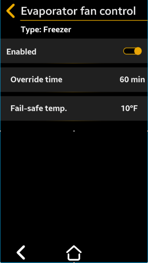
Evaporator Fan Switch Setup
Used to set the parameters to control the evaporator fans upon entry into the cold room. To avoid displacing cold air with warm air when users are opening the door, press Evap. Fan Switch and the evaporator fans will stop blowing. The fan will restart according to user-selectable time and temperature conditions.
= Enabled
= Disabled (Default)
Override time- Select to minutes between 1 to 60 min. of
fan “Off” duration, after which the fan
automatically turns back “On”
Default = 5min
Temp fail-safe- Select to the desired temperature
between 35 and 90°F at which the fan
automatically turns back “ON”
Default = 45°F
Press " Save” to save, then “Back” “Back” to cancel the selection
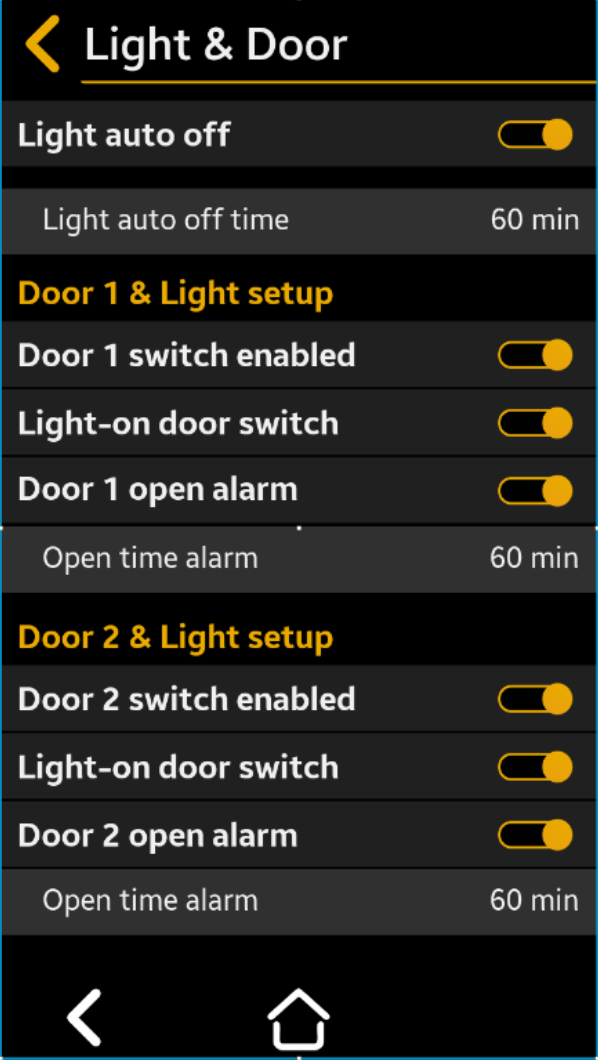
Light & Door Setup
Use to set the room’s lights control. Room lights are controlled by the TFT light button and can
be automatically turned on or off by other user selectable settings.
The door opening can turn on the light if to the door switch is enabled. The motion detector can
turn the light on if enabled and motion is detected in the room.
The light will be automatically turned off after a user selectable time.
Light Auto Off Enabled
= On
= Off
Default = No
If enabled, the light will automatically turn off after the user selectable time expires.
Light Auto Off Time- Select to desired minutes between 1
and 60 min. after which the light
automatically turns “OFF”
Default = 30 min
Press " Save” to save, then “Back” “Back” to cancel the selection
Door 1 Switch Enabled
= Enabled (Default)
= Disabled
Enabled means that the door switch is installed and active.
= Enabled (Default)
= Disable
When enabled, the light will automatically turn on when the door is opened
= Enable (Default)
= Disable
When enabled, an alarm is generated if the door is left open for a period of time exceeding the user selected “Open Alarm Time.”
Select to desired minutes between 1
and 60 min. of delay before Door
Open Alarm activates
Press " Save” to save, then “Back” “Back” to cancel the selection
Door 2 Switch Enabled - Repeat the procedure as for Door #1
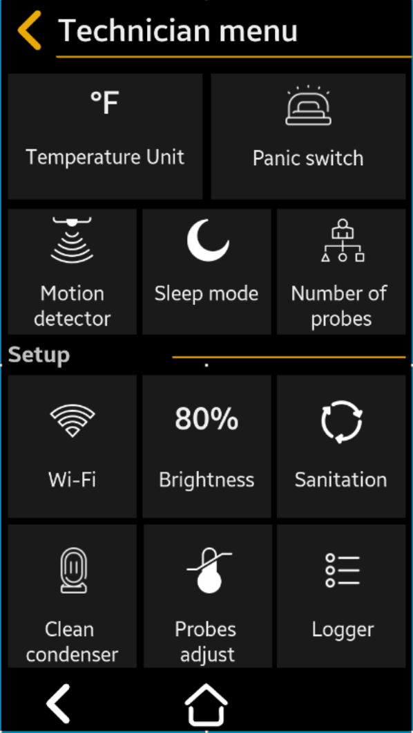
Technician Menu
The technician menu is used to set the system, usually when it is installed.
Warning
Do not modify these settings unless qualified and authorized to make these changes.
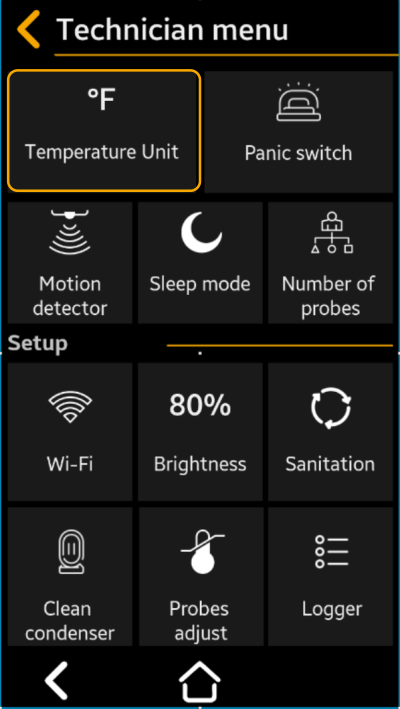
Temperature Unit
Use it to set if the temperature is displayed in °F or °C.
Select to °F (Default) or °C
Press " Save” to save, then “Back” “Back” to cancel the selection
This is example of how values are being modified inside menu sections
Value: 45°C - is the value you want to set your parameter
Value: 999 (Min) & 999 (Max) - represents the interval of the minimum and maximum values.
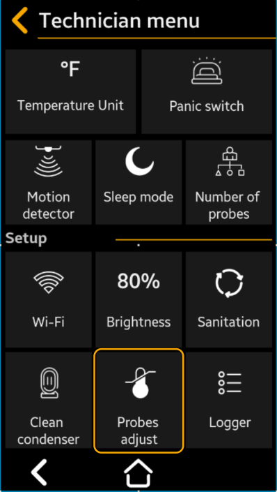
Probe Adjust
Use this parameter to compensate for any differences between the measured temperature at the probe location and the temperature displayed on the TFT (in case the probe cannot be positioned in the exact desired position or in similar situations).
Note
There is no need to compensate for the cable lengths, because the system uses calibrated digital sensors both for temperature and humidity.
Select to the desired temperature
reading offset, between -10° and
+10° if necessary
Default = 0.0°
Press " Save” to save, then “Back” “Back” to cancel the selection
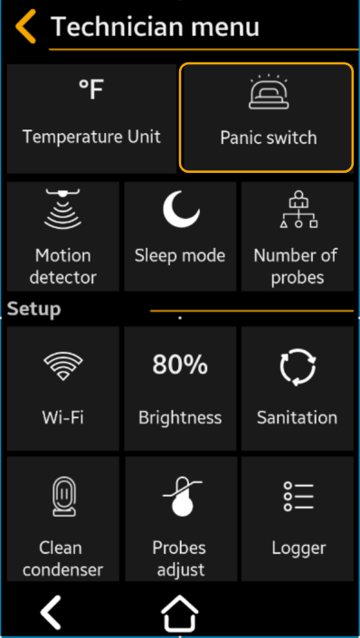
Panic Switch
Set this parameter to Enabled – Yes if the Panic Switch is installed.
Select to Yes or NO
Default = NO
Press " Save” to save, then “Back” “Back” to cancel the selection
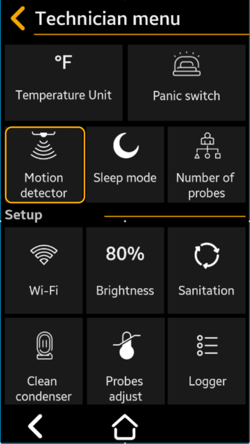
Motion Detector
Set this parameter to Enabled – Yes if the Motion Detector Switch is installed. The motion detector will switch the light on and keep it on as long as motion is detected in the room.
Select to Yes or NO
Default = YES
Press " Save” to save, then “Back” “Back” to cancel the selection
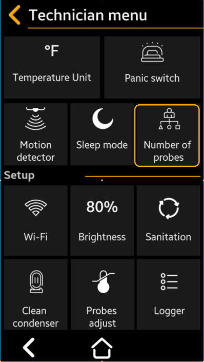
Number of Probes – Select to 1 or 2 (Default = 1)
The number of probes corresponds to the number of rooms to be monitored. One probe can be mounted per room. The probe contains 1 temperature sensor and one humidity sensor.
Select to 1 or 2
Default = 1
Press " Save” to save, then “Back” “Back” to cancel the selection
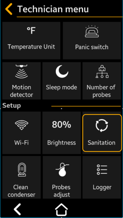
Sanitation Cycle Setup 3.2.6
Use this menu to set up to 30 sanitation cycles. The user can set the cycle start time and duration.
Select to Yes or NO
Default = No
Press " Save” to save, then “Back” “Back” to cancel the selection
Cycle #1
Select to the desired time of day cycle starts
Select to the number of minutes cycle lasts between 00:00 and 60:00 Format: MM SS Note. Maxim duration can be set to 60:00 (60 min. and 00 sec.)
Press " Save” to save, then “Back” “Back” to cancel the selection
Cycle #2 - #30 - Repeat as for Cycle #1
Press "Next to navigate to the next cycles screen
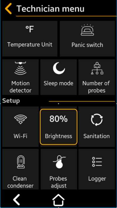
Brightness – Select to % TFT Brightness
This setting allows the user to adjust the brightness of the TFT display screen to compensate for high or low ambient light conditions, or to prolong the life of the display.
Select to the desired brightness level between 5 and 100% Default = 75%MAdvise.
Use 100% when using the room outside.
Using lower brightness levels will prolong the TFT lifetime.
Press " Save” to save, then “Back” “Back” to cancel the selection
Wi-Fi Setup
Use this menu to:
- enable the Wi-Fi connection for the system
- setup de Wi-Fi connection
- visualize the Wi-Fi settings (if already connected)
- Visualize device connection information: Device ID and Device Wi-Fi MAC; these information are coded in a scannable QR code, also.
To setup the Wi-Fi connection you can use the Smartrite Mobile App, also, but only if the Wi-Fi connection is set to active!
Use this information to add the device on the server using the Smartrite Mobile app!
Note
You can quickly access this menu from the Home screen, if you press Wi-Fi Connection icon .
Note
You can quickly access this menu from the Home screen, if you press Wi-Fi Connection icon

Wi-Fi Enable
Select the switch button to activate / disactivate the Wi-Fi connection

 = Enabled
 = Disabled (Default)
Press " Save” to save, then “Back” “Back” to cancel the selection
Note
If the Wi-Fi is disabled, the connection to the server will be lost, but the last network the device was connected to will still be stored in the systems memory. Therefore, if you will enable again the Wi-Fi connection, the system will automatically connect to the previous SSID.
This does not apply if you press the forget button 
Wi-Fi Settings
The system automatically populates the following information: Connected Wi-Fi name (SSID)
Device IP address
Device subnet mask
Gateway IP address
Wi-Fi Signal Strenght (RSSI) indication in dB
(ex: -75 dB)
(ex: -92 dB)
This means that the user must improve the Wi-Fi signal near the Smartrite device (place the AP closer to the Smartrite or mount a supplementary AP)
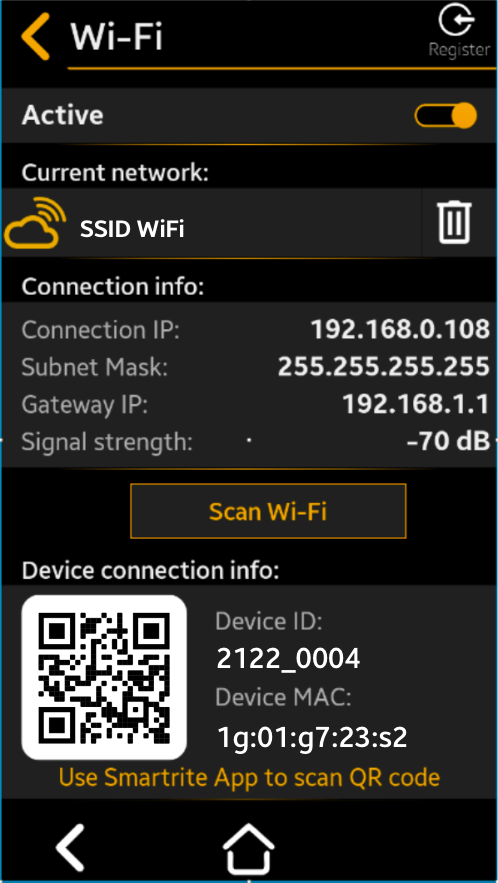
Scan for other Wi-Fi networks
Click this button, and the device will scan for the available Wi-Fi networks within its range and show them in a list ordered by signal strength, with the strongest signal shown first.

At the top of the list, the current network (SSID) to which the system is connected is indicated.
Click ![]() to modify the current network connection settings.
to modify the current network connection settings.
Click to forget the current network.
Below that, a list of up to 20 available Wi-Fi networks within the device's range is displayed. These networks are ordered by signal strength, with the strongest signal shown first.
Click the desired SSID and the device will ask you to setup the connection parameters.
Note
The device only supports 2.4GHz Wi-Fi networks.
Click  to rescan for the available Wi-Fi networks within the device range.
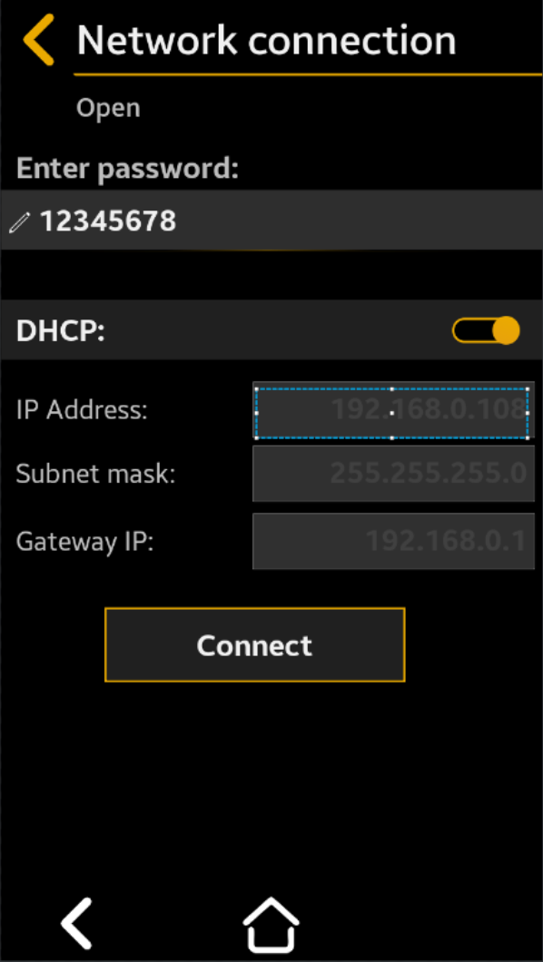
Network connection
Beneath the Network connection title, the Wi-Fi network's security level is indicated, whether it's open, encrypted, etc.
- Enter password
If the network in encrypted, you are asked to enter the network password
- DHCP
If DHCP is activated 
the router will set the connection parameters (device IP address, subnet mask, and gateway IP).
If DHCP is deactivated 
the device will prompt you to manually set the Device IP address, Subnet mask, and Gateway IP for the Wi-Fi connection to the router.
.
After everything is set, click Connect to establish a connection to the selected Wi-Fi network using the parameters you entered.
Forget current network
This system indicates:
- The Wi-Fi network name (SSID) to which it is currently connected
- The corresponding icon for the
- Wi-Fi connection state -see link to Current connection info:
When you click this button, you select the Forget current Wi-Fi network option. The device will remove the saved information about that network from its memory. This includes the network's name (SSID) and its password.
Note
To reconnect to this Wi-Fi network, you will need the password, so use this option with care.
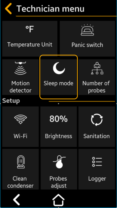
Sleep Mode
The function allows the Technician to put the system into a Sleep Mode when the unit is powered down to conserve the battery. Use this mode during shipment or other extended off periods to conserve battery. To use this mode the system must be operating on battery backup (power off).
Power off the system when you need to work on the electrical wires connected to it. If the system has a battery backup follow up the power down procedure
- Disconnect the system from the mains.
- Turn on the sleep mode: from the TFT access Menu->Sleep Mode
Warning
In Sleep mode battery is disconnected from the base module. To reconnect the back-up battery just plug the main power to the system.
Select to Yes or NO
Default = No
Press " Save” to save, then “Back” “Back” to cancel the selection
Note
If you will enter this mode with the mains power on, the system will run a hardware reset only�
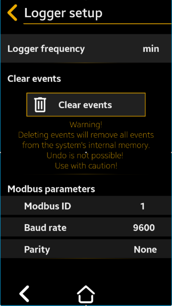
Logger Setup
This screen contains:
- the setup parameter that determines how often the functional data (called periodic events) are stored in the system memory and on the cloud server (if the system is connected to the Internet).
- Clear events function –clears all functional events stored in the device’s internal memory.
- Modbus parameters are used for the device to connect to a PC through the serial connection using the Modbus RS485 protocol.
Note
Over 100,000 periodic events are stored in the internal memory; ALL events (periodic events plus alarms) for 1 year of functioning can be stored on the cloud server.
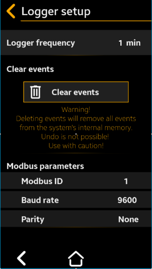
Logger Frequency
Select to frequency, in minutes
between 1 and 60 min., for data
collection
Default = 15 minutes
Press " Save” to save, then “Back” “Back” to cancel the selection
Clear Events
Select Yes to No
Default: No
When set to YES, all the functional events will be cleared from the device's internal memory.
Note
Note. The events transferred in the cloud will not be deleted using this function!
Press " Save” to save, then “Back” “Back” to cancel the selection
Modbus parameters
Select to choose the desired device
serial ID from 1 to 255
Default: 1
Select to choose the serial
communication speed between
9600, 19200 or 38400
Default: 9600
Select to choose the communication
parity between None, Even or Odd,
according to the PC software
requirements
Default: None
Press " Save” to save, then “Back” “Back” to cancel the selection
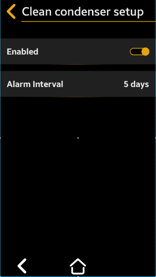
Clean Condenser Setup
This parameter allows the operator / Technician to set a repeating condenser cleaning interval reminder.
Select to Yes or NO
Default = Yes
Press " Save” to save, then “Back” “Back” to cancel the selection
Select to number of days (between 1
and 60 days) between cleanings
Default = 30 days
Save” to save, then “Back” “Back” to cancel the selection
Change Password
This may be used for customization of the password for the programming menu. The password is a 4 digit (numerals 0 -9) pin.
Note
The factory default password is 1234.
Then press "OK"
EX: 2345
Then press "OK"
EX: 2345
Then press "OK"
The new password is saved and the system automatically returns to Settings Screen
Select Language
Select to English or Spanish
Default = English
Press " Save” to save, then “Back” “Back” to cancel the selection
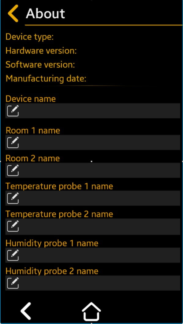
About
This menu centralizes all general information and main settings with the possibility to edit the information about the device..
To edit the device information, simply press ![]() to edit the desired field.
to edit the desired field.
Press "Back" to go to the main Menu Settings
Note
All parameters can be set using web application.
smartrite.everidge.com -> Devices -> Select Device -> Press Show Parameters button
Maximum field length: 16 chars